MIL-PRF-28861/12G
Dash number
Configuration
001 thru 016
A
B
Circuit
A
033 and 034
diagram
±.005
Ref
017 thru 032
L
.200
.715
B
035 and 036
C
.110
.625
Inches
mm
Inches
mm
.002
0.05
.156
3.96
.005
0.13
.200
5.08
.020
0.51
.250
6.35
.030
0.76
.625
15.88
.110
2.79
.715
18.16
.128
3.25
NOTES:
1. Dimensions are in inches.
2. Metric equivalents are given for general information only.
3. Unless otherwise specified, tolerance is ±.005 (0.13 mm).
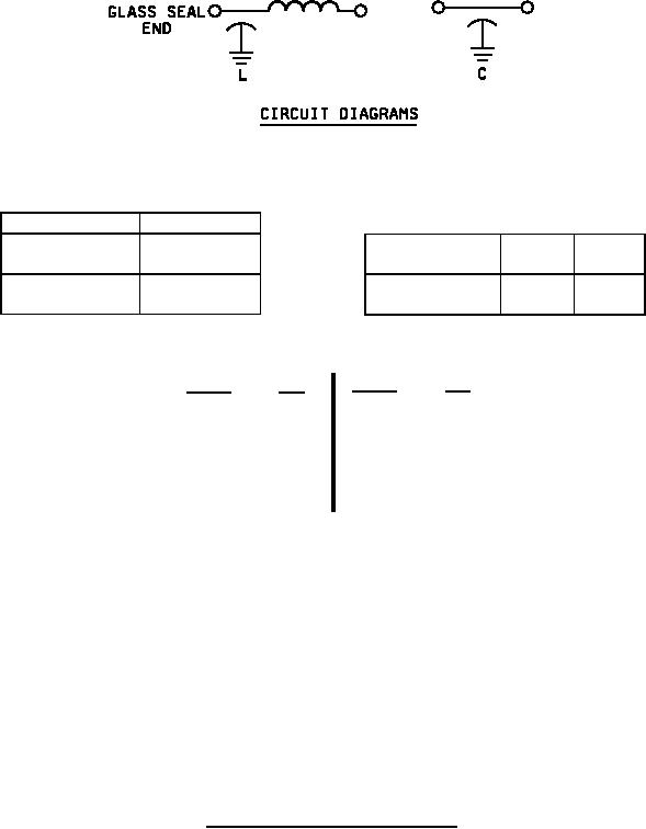
4. Circuit diagrams are for information only.
5. Filters shall be supplied with 60/40 solder preform.
6. Potting on non-hermetically sealed end shall not extend beyond .030 inch (0.76 mm) from the filter body.
7. Filters shall be installed using the recommended installation methods (solder-in style of MIL-PRF-28861).
FIGURE 1. Case dimensions and circuit diagrams - Continued.
2
For Parts Inquires submit RFQ to Parts Hangar, Inc.
© Copyright 2015 Integrated Publishing, Inc.
A Service Disabled Veteran Owned Small Business