MIL-PRF-28861D
4.6.5.1 Insertion loss (at temperature). This test may be conducted in conjunction with the capacitance
measurement (temperature and voltage) provided the insertion loss is read before the dc bias is applied at each
temperature. Filters shall be tested as follows:
a. The filters shall be located with an appropriate adaptor in a temperature chamber.
b. Load and no-load measurements shall be made at -55°C, +25°C, and +125°C. Measurements shall be
taken at a sufficient number of frequencies to plot a curve of insertion loss versus frequency over the
specified frequency range for each temperature. Alternatively, photographs of the display of a spectrum
analyzer or chart recordings may be used.
4.6.6 Voltage drop (see 3.11).
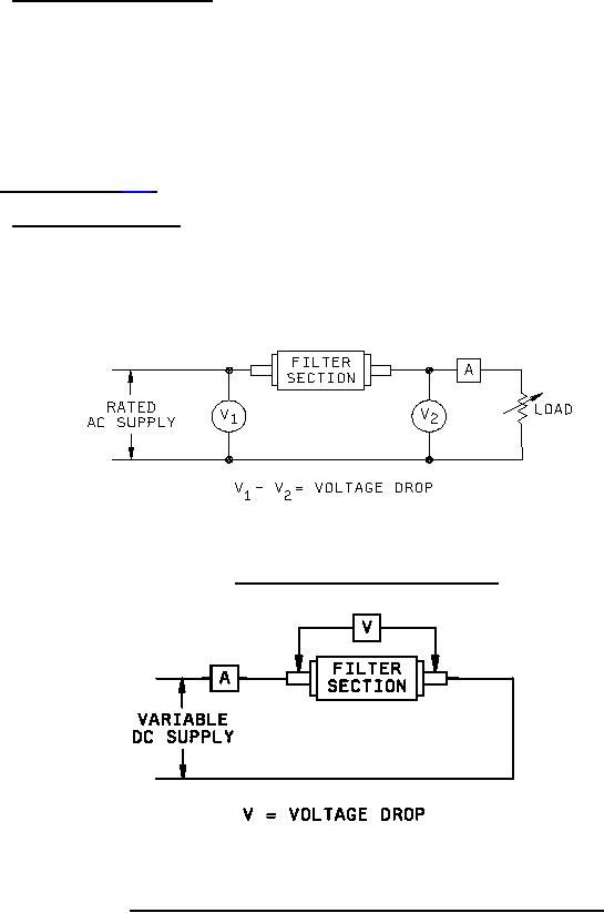
4.6.6.1 Voltage drop for ac filters. The voltage drop is the difference between the input voltage to the filter and the
output voltage of the filter when the filter is carrying rated current at rated voltage, with a resistive load at maximum
rated frequency (see 3.1). The method of voltage measurement is shown on figure 2. Measurements shall be made
by using equipment that will enable voltage differences of less than 0.1 volt to be read.
FIGURE 2. AC filters; measurement of voltage drop.
FIGURE 3. DC filters; measurement of series-element voltage drop at rated current.
23
For Parts Inquires submit RFQ to Parts Hangar, Inc.
© Copyright 2015 Integrated Publishing, Inc.
A Service Disabled Veteran Owned Small Business