MIL-PRF-28861D
in a static or tunnel oven for approximately a 40-minute period at +160°C to the joint. Cool the assembly slowly (see
6.6.1.3.1).
6.6.2 Soldering to the filter leads (all styles). All solder connections made to the terminals of the filter should be
performed with solder that is liquid at temperatures less than +232°C, and soldering heat applied only long enough to
make a good solder connection. Use a heat sink on the lead next to the filter body. Preheating the filters to +125°C
for 5 minutes is recommended when possible to prevent thermal shock of the ceramic materials. Do not
bend or twist the leads or terminals of the filters as this will result in cracked seals or ceramic capacitors.
6.7 Outgassing (option). As an option for inspection to outgassing requirements of 3.4.2, a minimum of 10 grams
of each polymeric material in its final processed condition may be submitted to the following NASA installation for
outgassing test: Director, Material and Processes Laboratory, EH01, Marshall Space Flight Center, Huntsville, AL
35812. As an alternative, a minimum of a single device utilizing each material may be submitted to Marshall Space
Flight Center for outgassing tests in 4.6.28.
6.8 Subject term (key word) listing.
EMI
Feed-through, filter
Insertion loss
Low pass, filter
RFI
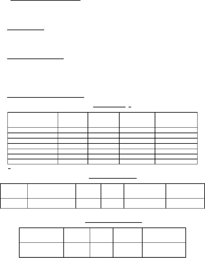
6.9 Specification sheets arranged by function. See tables X, XI, and XII.
TABLE X. Broadband types. 1/
Circuit
Minimum
Specification
Voltage ratings
Current
diagrams
capacitance
sheet
(volts)
ratings
(µF)
(amperes)
L1, L2, š
70 V dc
.1 to 5.0
.7,
1.4
L1, L2, š
100 V dc
.25 to 5.0
.45, .90
L1, L2, š
150 V dc
.1 to 5.0
.25, .50
L1, L2, š
200 V dc/125 V ac
.25 to 5.0
.15, .30
50 V dc, 70 V dc,
15
L2, C
.001 to 1.2
100 V dc, 150 V dc
15
L2, C
.001 to 1.2
MIL-PRF-28861/1
200 V dc/125 V ac
15
L2, C
.001 to 1.2
MIL-PRF-28861/1
1/ Hermetically sealed.
TABLE XI. High frequency bolt types.
Thread
Voltage rating (volts)
Current
Circuit
Minimum
Specification
series
rating
diagrams
capacitance
sheet(s)
(amperes)
1000 pF to .045 µF
.112-40
100 V dc and 200 V dc
5
L2, C
UNC-2A
TABLE XII. High frequency solder-in types.
Voltage rating
Current
Circuit
Minimum
Specification
(volts)
rating
diagrams
capacitance
sheet
(amperes)
50 V dc, 100 V dc
5
L, C
10 pF to
and 200 V dc
15,000 pF
36
For Parts Inquires submit RFQ to Parts Hangar, Inc.
© Copyright 2015 Integrated Publishing, Inc.
A Service Disabled Veteran Owned Small Business