MIL-PRF-15733J
4.6.10 Overload (see 3.13). Filters shall be suspended by their conductors in free air at an ambient temperature of
20°C minimum. A current equal to 140 percent of rated current at maximum rated frequency shall then be applied for
15 minutes. After the filter has returned to room temperature, the insulation resistance and voltage drop shall be
measured as specified in 4.6.7 and 4.6.8, respectively. Filters will be visually examined for evidence of physical
damage.
4.6.11 Terminal strength (see 3.14). Filters shall be tested in accordance with method 211 of MIL-STD-202. Test
condition A, B, or E shall apply as specified in the individual specification sheet.
4.6.11.1 Pull. A force of the specified magnitude shall be applied to the terminal at the point where the lead from
the external circuit connects to it. The force may be applied in any direction, including the weakest, and shall be
increased gradually to the specified magnitude and held at that value for at least 30 seconds (see 3.1).
4.6.11.2 Bend (applicable only to solder-lug terminals). Any terminal that shows visible bending in the terminal-pull
test (see 4.6.11.1) shall be bent back and forth five times to an angle of 45° each side of center (terminal bend
through an arc of 90°).
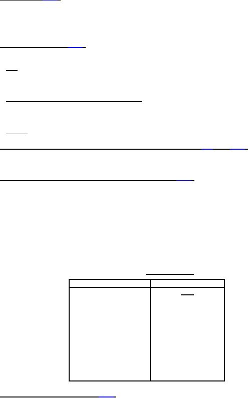
4.6.11.3 Torque. Terminals with external screw threads shall be subjected to the torque specified in table VIII.
4.6.12 Flashpoint of impregnant or potting compound (when specified; see 3.1) (see 3.15). The flashpoint of the
impregnant or potting compound shall be measured as specified in ASTM-D92-78. However, the paragraphs
covering firepoint and precision do not apply to this test.
4.6.13 Resistance to soldering heat (soldered terminals only) (see 3.16). Filters shall be tested in accordance with
method 210 of MIL-STD-202. The following details shall apply:
a. Depth of immersion in the molten solder shall be to a point .062 ± .031 inch (1.59 ± .79 mm) from the
insulation.
b. Test condition letter: B.
c. Cooling time prior to final examinations and measurements: Sufficient time shall be allowed to stabilize
the filters at room ambient temperature. Filters shall then be physically examined for evidence of
physical damage and capacitance to ground and coil continuity shall be checked.
TABLE VIII. Terminal torque
Screw size
Torque
lb-in
9
6-32
14
8-32
18
10-32
30
1/4-20
50
5/16-24
100
3/8-24
150
7/16-20
250
1/2-20
200
1/2-28
23
12-28
1/4-28
40
4.6.14 Salt atmosphere (corrosion) (see 3.17). Filters shall be tested in accordance with method 101 of MIL-STD-
202. The following details and exception shall apply:
a. Test condition letter: As specified (see 3.1).
b. Measurements after exposure: Not applicable.
15
For Parts Inquires submit RFQ to Parts Hangar, Inc.
© Copyright 2015 Integrated Publishing, Inc.
A Service Disabled Veteran Owned Small Business